

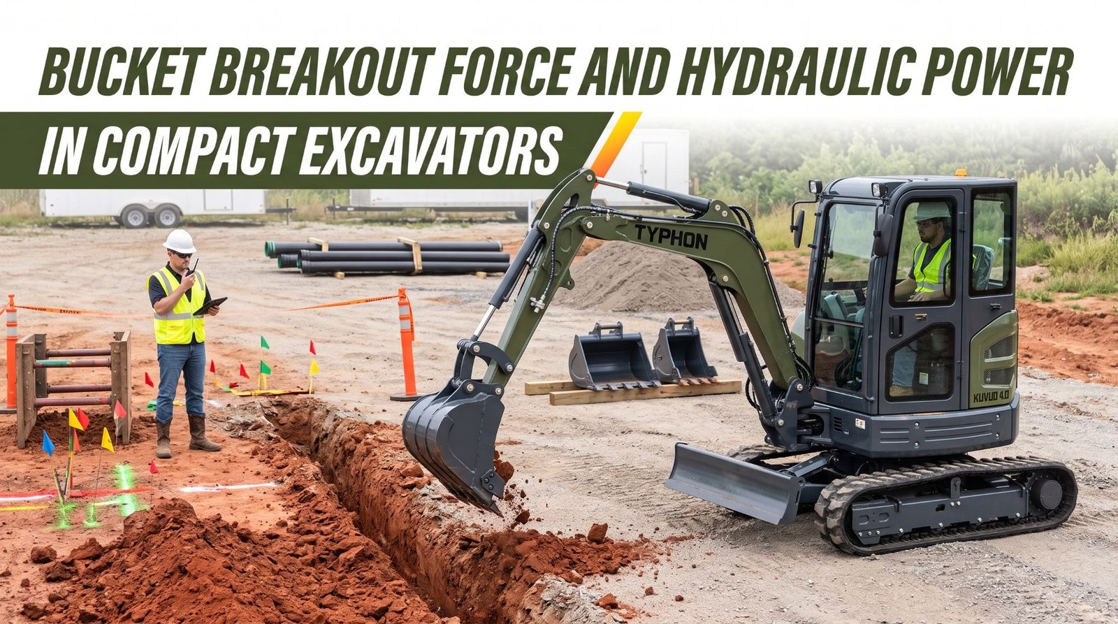
A compact excavator earns its keep when the ground pushes back. In compacted clay at a footing excavation, frozen topsoil on a winter utility job, or an old road base beside a curb line, the bucket teeth have to bite and tear material loose without stalling. When the machine has enough digging force for the task, the operator fills the bucket in one smooth curl and moves on. When it doesn’t, the bucket skates across the surface, the tracks lift, and every cycle takes longer than it should.
Bucket breakout force and hydraulic power are the specifications buyers use to judge that capability. Breakout force describes how hard the bucket can push into or pry out material. Hydraulic power describes how the machine supplies the pressure and flow behind every movement, from boom raise to swing to a breaker on the auxiliary circuit. Both appear prominently on specification sheets, and both are easy to misread. A high pressure rating doesn’t guarantee strong digging, and a high flow figure doesn’t guarantee a fast or well-controlled machine.
Real digging performance comes from several factors working together. Cylinder bore and rod diameter turn pressure into force. Linkage geometry and boom position decide how much of that force reaches the bucket teeth. Operating weight and track grip decide whether the machine stays planted when the teeth meet resistance. Bucket width and tooth design decide how that force is spread across the cutting edge. Two machines with similar headline numbers can feel very different in the same trench.
What Bucket Breakout Force Measures
Bucket breakout force is the force an excavator can apply at the bucket’s cutting edge or teeth under defined test conditions. On most specification sheets, it appears alongside a second figure, arm digging force, sometimes called arm crowd force or stick force. The two describe different motions. Bucket digging force comes from the bucket cylinder curling the bucket. Arm digging force comes from the arm cylinder pulling the arm toward the machine. Operators use both throughout a typical digging pass, so both deserve attention.
In practical terms, bucket digging force shows how well the machine can penetrate compacted soil, pry loose embedded material, and break out a full bucket at the end of a pass. Arm digging force shows how well the machine can drag the bucket through the cut and maintain a steady trench floor. A machine with strong bucket force but weak arm force may break material loose easily but struggle to pull a long, deep pass. The reverse can leave the bucket stalling at the moment it needs to curl a full load.
Breakout force is also a maximum under specific conditions, not a constant. The published figure is usually taken at the point in the stroke where the linkage provides the best leverage. As the bucket and arm move through their range, available force rises and falls.
Key takeaway: Breakout force describes the force available at the bucket teeth under defined test conditions, so compare bucket and arm digging forces under the same standard, note whether boost is included, and remember the published figure is a maximum, not a constant.
Hydraulic Pressure and Cylinder Force
Every digging movement on a compact excavator starts with pressurized oil acting on a cylinder piston. The force that cylinder produces follows a simple relationship: hydraulic pressure multiplied by the area the pressure acts on. Higher pressure or a larger piston area produces more force. That relationship explains why pressure alone can’t tell you how hard a machine digs.
That difference matters because excavator linkages are designed around it. On a typical compact excavator, curling the bucket and pulling the arm in are driven by cylinder extension, which uses the full bore area and delivers the most force. Manufacturers choose bore and rod sizes to balance force, speed, oil volume, and the cylinder’s resistance to bending under load.
The force at the cylinder isn’t the force at the bucket teeth. Between them sits the linkage, which acts as a lever system. In most excavator designs, the cylinder pushes on a short lever arm while the bucket teeth sit at the end of a much longer one. That arrangement trades force for movement, giving the bucket a wide range of motion but reducing the force at the cutting edge.
System pressure has limits, too. A main relief valve caps maximum pressure to protect the pump, hoses, cylinders, and structure. Pressure losses through valves, hoses, and fittings reduce what actually reaches the cylinder. Some machines include a power boost function that briefly raises relief pressure for heavy digging, which is why boosted figures appear on some specification sheets.
Never adjust relief valve settings to gain digging force. Raising pressure beyond design limits overloads hoses, seals, pins, and structural components and can cause sudden failures. Relief settings should only be checked by qualified technicians using the manufacturer’s procedures and test equipment.
Key takeaway: Cylinder force equals pressure multiplied by piston area, so bore and rod diameter matter as much as pressure, and linkage leverage reduces that force before it reaches the teeth, which is why a high pressure rating alone never guarantees strong digging.
Hydraulic Flow and Machine Response
If pressure decides how hard a cylinder can push, flow decides how fast it moves. Hydraulic flow, usually stated in gallons per minute, is the volume of oil delivered to the system over time. A cylinder extends at a speed set by how quickly oil fills the space behind its piston, so more flow means faster movement for the same cylinder.
Flow also shapes how the machine feels when several functions run together. A digging cycle blends boom, arm, bucket, and swing. When combined demand exceeds pump output, flow must be shared. Many modern compact excavators use load-sensing or flow-sharing hydraulic systems that distribute flow in proportion to lever position, so movements are slow and even rather than one function stalling while others race. Others use open-center or multi-pump designs with their own characteristics. Each approach has trade-offs, and the quality of the control valves often matters as much as the pump size.
Fast isn’t always better. Precise grading, setting pipe, and digging beside exposed utilities depend on smooth, proportional control at low speeds. A machine that moves quickly but surges or jerks can slow skilled work and increase risk. During a demonstration, test fine control as well as cycle speed. Try feathering the bucket to grade a footing, and run combined boom and swing movements with a loaded bucket.
Key takeaway: Flow controls how fast cylinders and motors move, while pressure controls how hard they push, so evaluate flow, flow sharing, and engine capacity together and test both cycle speed and fine control during a hands-on demonstration.
Boom, Arm, and Bucket Geometry
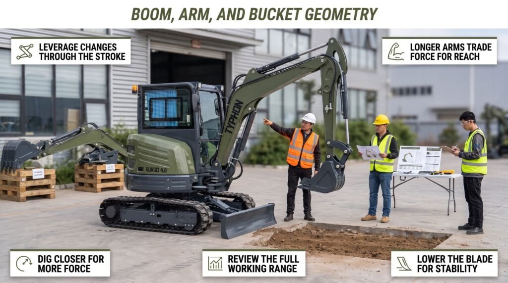
Geometry determines how cylinder force becomes digging force. The pivot locations, boom length, arm length, cylinder mounting points, and bucket linkage all shape the leverage available at each point in the digging cycle. Because those leverage relationships change as the machine moves, digging force is never the same across the whole working range.
Bucket linkage offers a clear example. As the bucket curls, the angle between the bucket cylinder and its linkage changes constantly. Near the middle of the stroke, the linkage often provides its best mechanical advantage, which is where manufacturers usually measure peak bucket digging force. Near the start or end of the curl, the angle is less favorable, and available force can drop noticeably. Operators feel this as a bucket that tears through the middle of a pass but struggles to break out a load at full curl.
Arm length creates a similar trade-off. Many compact excavators offer a standard arm and a long arm. A long arm increases maximum digging depth, reach, and dump height, which helps on deep utility trenches and wide excavations. It also places the bucket farther from the arm cylinder’s pivot, reducing arm digging force. On many machines, the long arm configuration publishes a lower arm digging force than the standard arm. The bucket digging force may stay similar, but the load on the bucket also affects lifting capacity and stability at reach.
Boom position adds another layer. Digging close to the machine with the arm pulled in generally places the bucket where the boom and arm cylinders work with good leverage and the machine’s weight resists the digging reaction effectively. Digging at full reach with the arm extended spreads the same cylinder force across longer lever arms, reducing force at the teeth. A crew trenching for a drainage line often finds the machine digs strongly within the first several feet of reach and noticeably slower at full extension in the same soil.
Machine weight and stability set the final limit. Digging force pushes back on the excavator. If the bucket meets more resistance than the machine’s weight and track grip can hold, the tracks lift, the machine slides toward the cut, or the upper structure rocks. At that point, extra hydraulic force achieves nothing. Lowering the dozer blade to the ground on the digging side, positioning the machine on firm, level ground, and digging closer to the tracks all help the machine use its available force.
Review the full working range diagram and digging force specifications, not just a single maximum figure. Ask whether the published forces apply to the arm and bucket you plan to use, and compare depth and reach requirements against the force trade-offs of each configuration.
Key takeaway: Linkage geometry, arm length, and boom position change how much cylinder force reaches the teeth at every point in the cycle, and machine weight sets the limit on usable force, so review the full working range rather than relying on one peak figure.
Matching Bucket Size to Excavation Conditions
The bucket is where all of the machine’s digging force finally meets the ground. Its width, profile, weight, and tooth arrangement decide how efficiently that force breaks material loose. The right bucket lets a machine perform near its potential. The wrong one wastes force, slows cycles, and adds stress to the hydraulic system and structure.
Teeth multiply this effect. Each tooth concentrates force on a small point, which is why toothed buckets bite into hard material far better than smooth-edge buckets. Sharp, well-maintained teeth penetrate more easily than worn, rounded ones. Smooth-edge and ditch cleaning buckets suit grading, cleanup, and finishing work in softer soil, where a clean floor matters more than penetration. Rock buckets use heavier construction, reinforced edges, and narrower or more aggressive teeth for hard and abrasive material.
Bucket weight and capacity affect the machine in other ways. A heavy or oversized bucket uses part of the hydraulic force just to move itself and adds to the load on the boom, arm, and pins. A full oversized bucket of dense material can also exceed what the machine can lift and swing stably, particularly at reach or over the side. Every pound of bucket and coupler weight counts against lift capacity and must be accounted for when reading the lift chart. Use only buckets within the manufacturer’s approved size and weight range for the machine.
Inspect buckets regularly. Check teeth, adapters, retaining pins, cutting edges, side cutters, and wear plates, and replace worn components before they reduce penetration or damage the bucket. After every bucket change, confirm that the quick coupler’s locking mechanism is fully engaged according to the manufacturer’s procedure, then test the bucket gently against the ground before digging.
Key takeaway: Narrower buckets and sharp teeth concentrate breakout force for hard ground, while wider buckets suit loose material, so match bucket width, profile, and weight to the soil and trench requirements and stay within the manufacturer’s approved limits.
Evaluating Hydraulic Performance for Attachments
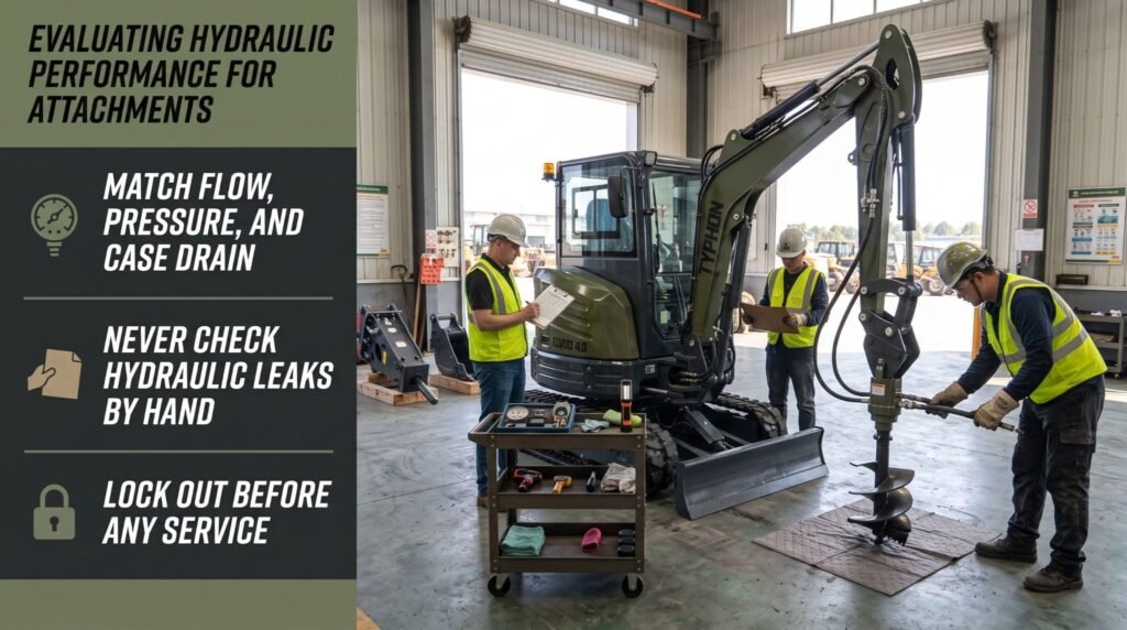
Compact excavators often do far more than dig with a bucket. Hydraulic breakers, augers, thumbs, grapples, compaction plates, tilt buckets, mulchers, and rotating tools all run from the machine’s hydraulic system. Each attachment has its own flow, pressure, return, and connection requirements set by its manufacturer. Matching those requirements to the machine decides whether the attachment performs well, overheats, or fails early.
Flow and pressure come first. Every powered attachment publishes a minimum and maximum operating flow and a pressure range. If the machine delivers too little flow, the attachment runs slowly, stalls under load, and may cut or break poorly. If it delivers too much, motors can overspeed and excess oil passes over relief valves, generating heat. Many compact excavators allow auxiliary flow to be adjusted from the operator’s station or through service settings, so confirm the adjustable range and set it to the attachment’s requirements.
Return and case drain requirements are just as important and are often overlooked. Hydraulic breakers usually need one-way flow with a low-restriction return path, ideally directly to the tank, because back pressure reduces breaker performance and can damage seals. Many hydraulic motors used in augers, mulchers, and similar tools require a case drain line that carries internal leakage oil back to the tank at very low pressure. Without a correctly connected case drain, pressure can build inside the motor housing and blow out the shaft seal. Confirm whether the machine provides a case drain port and whether the auxiliary circuit can be set for one-way or two-way flow.
Connections and controls complete the match. Check coupler types and sizes, since many machines use flat-face couplers that reduce leakage and contamination. Attachments with tilt, rotate, or electrically controlled functions may need a second auxiliary circuit and specific electrical connectors. Confirm that the attachment’s mounting matches the machine’s quick coupler or pin size, and that its weight suits the machine’s capacity and stability.
Connecting and servicing attachments must be done safely. Lower the attachment to the ground, shut down the engine, and relieve auxiliary circuit pressure as the manufacturer instructs before connecting or disconnecting couplers. Clean couplers before connecting them, and route hoses with enough slack that they won’t pinch or stretch through the full range of movement. Never adjust relief settings to force an attachment to work.
Never use your hand to search for a hydraulic leak. Fluid escaping through a pinhole under pressure can penetrate skin and cause an injection injury. The wound may look minor at first, but it’s a medical emergency that requires immediate surgical treatment. Use a piece of cardboard or wood, and wear gloves and eye protection. If anyone is struck by escaping fluid, get emergency medical care at once and tell medical staff it’s a hydraulic injection injury.
Before any service or inspection, lower the boom, arm, bucket or attachment, and dozer blade fully to the ground. Shut down the engine, remove the key, relieve hydraulic pressure according to the manufacturer’s procedure, and apply your personal lock and tag. Never work beneath a raised boom or arm held only by hydraulics.
Key takeaway: Match each attachment’s flow, pressure, return, case drain, coupler, and electrical requirements to the machine before use, confirm continuous hydraulic power and cooling capacity, check leaks with cardboard rather than your hands, and lock out before any service.
Conclusion
Bucket breakout force and hydraulic power describe connected but distinct parts of compact excavator performance. Breakout force shows the push available at the teeth under defined conditions, while pressure, cylinder bore, and rod diameter determine the force each cylinder can produce. Flow determines how quickly the machine moves and how smoothly functions combine. Linkage geometry, arm length, and boom position decide how much cylinder force actually reaches the bucket at each point in the cycle, and machine weight decides whether that force can be used. Bucket selection and attachment matching turn all of these factors into productive work on real ground.
Frequently Asked Questions
Does higher hydraulic pressure always mean stronger digging force?
No. Cylinder force equals pressure multiplied by piston area, so bore and rod diameter matter as much as pressure. Linkage geometry then reduces that force before it reaches the teeth, and the reduction changes with bucket and boom position. Arm length, bucket design, and machine weight also affect usable digging force. A machine with lower system pressure but larger cylinders or better leverage can outdig one with a higher pressure rating.
What is the difference between hydraulic flow and pressure?
Flow, measured in gallons per minute, is the volume of oil moving through the system, and it controls how fast cylinders extend and motors spin. Pressure, measured in psi, is the force the oil exerts, and it controls how hard cylinders push and how much torque motors produce. Hydraulic horsepower combines the two. A well-matched machine balances flow and pressure for both digging and attachment work, within the limits of its engine and cooling system.
Can any hydraulic attachment be used on a compact excavator?
No. Each attachment must match the excavator’s approved flow and pressure range, return requirements, case drain needs, coupler type, electrical connections, mounting interface, and weight limits. Breakers often need a low-restriction return to the tank, and many hydraulic motors need a dedicated case drain line to protect their seals. Confirm compatibility with both the machine and attachment manufacturers before installation, and never adjust relief settings to force a match.